
Yield Locus of Bulk Solids
Yield locus bulk solids ✓ Flow limit determination ✓ Shear tests ASTM D6682 ✓ Flow properties ✓ Stress state ✓ Material characterization
Fundamentals of Bulk Solids
A bulk solid consists of many non‑uniform particles. For material characterization it is useful to treat the assembly as a continuum to describe the overall behaviour rather than that of individual particles. Many factors influence bulk behaviour: moisture, temperature, particle size and shape, surface texture, mechanical properties (elastic, viscoelastic, plastic, brittle), chemical composition, gravity and interparticle forces such as electrostatic and Van‑der‑Waals forces.
The Yield Locus
The shear test simulates typical stress conditions that bulk solids experience in handling systems. Under applied stresses particles initially deform elastically and forces are transmitted even without relative particle movement. If stresses exceed a critical value, particles begin to move relative to each other (plastic deformation) – the bulk solid starts to shear or flow.
The resistance to fracture in the shear plane before flow depends strongly on packing density and prior consolidation. The bulk solid's packing density changes with load and motion and thus the flow limit depends on the stress state. Bulk solids can retain packing states after removal of the external load.
The yield locus describes the flow limit: the stress combinations at which the material is just about to move on the sliding plane under shear stress (τ). Higher packing densities usually increase interparticle contacts and raise the resistance to incipient flow.
Shear testers reproduce stresses in a defined manner and measure resulting flow properties. The test integrates all complex influencing factors and yields real material data used for further calculations.
Normal and Shear Stresses
For a volume element a boundary force (F) on area (A) splits into:
- normal force FN (perpendicular to A)
- and shear force FS (parallel to A)
Corresponding stresses are σ = FN/A (normal) and τ = FS/A (shear). Shear stresses primarily cause relative particle motion and plastic deformation.
Lateral Pressure Ratio
Applied forces distribute differently in different directions depending on material behaviour. The lateral pressure ratio is defined as λ = σh / σv (horizontal / vertical pressure). Note: in bulk solids mechanics compressive stresses are conventionally positive.
Two limiting idealised cases: λ=1 for an ideal liquid (no shear stresses), λ=0 for an ideally rigid solid. Real bulk solids may exhibit 0<λ<1 depending on packing and state.
Considering a frictionless boundary, the spatial normal stresses become the principal stresses σ1, σ2, σ3 with σ1 > σ3 > σ2. For engineering, σ1 and σ2 suffice and we speak of a plane stress state.
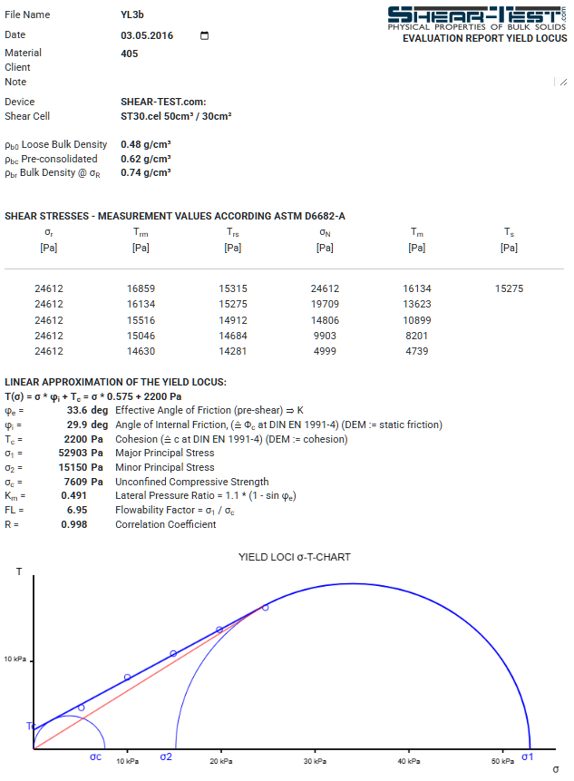
The Mohr Stress Circle
The Mohr stress circle (Christian Otto Mohr) graphically represents normal (σ) and shear (τ) stresses. It is the primary tool for visualising stress states and failure conditions in bulk solids.
Selecting the appropriate cut plane yields the plane stress state where σ1 and σ2 are extreme and shear vanishes. The Mohr circle is fully defined by σ1 and σ2. Tangency of the circle with the failure envelope gives the failure stresses (σ,τ) on the sliding plane; combinations on the Coulomb line cause flow.
The major consolidation stress σ1 determines consolidation and porosity and serves as basis for material functions. Constructing a Mohr circle with σ = 0 that also touches the yield locus yields the unconfined yield strength σc, relevant for arching and silo design.
Measurements of the Yield Locus with Shear Testers
Shear testers, adapted from soil mechanics (Jenike), measure shear strength for defined consolidation states. At several normal stresses the shear stress at incipient flow is recorded and the σ–τ points form the yield locus for that initial density. Repeating at different initial densities yields a family of yield loci.
Measured and evaluated data provide essential material parameters for characterisation and process design.
Key parameters:
- internal angle of friction (φi),
- effective angle of friction (φe), from which the lateral pressure ratio λ (or K) can be derived,
- cohesion (τc),
- unconfined yield strength (σc),
- flowability factor (FL or ffc),
- bulk density after consolidation (static and flowing state).
Effective Angle of Friction
The position of a yield locus depends on packing density / consolidation. A higher initial density shifts the yield locus upward. Because the application stress state is not known in advance, several yield loci at different reference stresses σr are measured to allow interpolation.
The effective angle of friction (φe) is a function tangent to the major Mohr circles of the measured yield loci. Using φe the lateral pressure ratio λ = σh/σv can be derived for stress states between measured loci.
Example: three yield loci (blue) of the same material at different reference stresses (σr) — effective yield locus (red)
Calculation of Stress States Between Measured Yield Loci
Principal stresses calculated from effective angle of friction σ1(φe), σ2(φe)
Unconfined yield strength derived via the flow function σd(σ1)
Professional Yield Locus Determination for Your Bulk Solid
Need precise characterisation of your bulk solid? Our laboratory performs standard‑compliant yield locus measurements and delivers detailed evaluation reports.
- ✓ Over 30 years of experience
- ✓ Standard‑compliant measurements
- ✓ Detailed evaluation reports