Silo Design for Mass Flow
Mass flow silos ✓ Design principles ✓ Mass vs funnel flow ✓ Bulk material measurements ✓ Material handling systems ✓ Practical applications
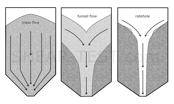
To avoid storage and discharge issues with cohesive bulk materials, silo design should preferably aim for mass flow. In mass flow the entire bulk material moves during discharge, preventing stagnant zones, segregation and arching.

Issues with funnel flow
In funnel flow only an inner core of material moves while stagnant zones remain at the walls. Typical consequences include:
- differing residence times up to dead zones
- segregation and quality loss
- increased dust formation and associated hazard
- eccentric arching and sudden collapse
- fluidization and unsteady discharge mass flows
- time-dependent consolidation
Early bulk material testing reduces failure risks and follow-up costs.
Limiting criterion for mass flow
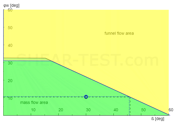
Assessment is based on measured material parameters (e.g. effective internal friction angle, wall friction angle, compressive strength). With these values an online calculation tool can determine the required hopper angle and suitable wall materials.
LIMITING CRITERIA FOR MASS FLOW / FUNNEL FLOW (Example)
| φe | φw | βcrit | Assessment | |
|---|---|---|---|---|
| Example material | 35.6° | 10.7° | 45.7° | MASS FLOW |

Excerpt from the automatic online silo calculation (simplified example).
With the measurement results (flowability, wall friction, density, cohesion) the necessary hopper angle and suitable wall material can be determined.
Measures to ensure mass flow
The design for mass flow requires a combination of correct geometry, appropriate wall materials, suitable discharge equipment and operating strategies. The most important action areas with concrete recommendations are listed below:
- Hopper geometry and outlet size: A sufficiently steep hopper angle and a generous outlet reduce the risk of arching and help activate the entire discharge area.
- Wall material and coatings: Smooth, low‑adhesion wall surfaces reduce wall friction and sticking, preventing funnel flow.
- Choose discharge equipment carefully: Appropriate discharge devices (e.g. screws, vibrators, conical valves, special slide gates) should be selected to activate as large a discharge area as possible and avoid eccentric emptying.
- Control ventilation and de‑aeration: Ventilation can ease discharge but may also cause fluidization. Design ventilation so it supports de‑aeration without promoting fluidization.
- Filling strategies: Controlled filling (e.g. ring feed / distributor systems) minimizes segregation during filling and reduces eccentric loads.
- Material modification: Adjustments such as granulation, drying or additives can change cohesion and moisture and reduce arching and time consolidation.
- Regular activation / maintenance: Periodic activation of the discharge prevents time consolidation and build‑up.
- Monitoring & measurement data: Continuous monitoring (level sensors, throughput measurement) and the use of measured material data allow early interventions and adaptive control.
- Testing in a measurement laboratory: For product changes or before final design, standardized tests (flowability, wall friction, time consolidation, bulk density) are recommended to validate assumptions.
This measures list is aligned with the disturbance patterns described on Silo Problems: appropriate hopper geometry prevents arching; the choice of discharge equipment reduces eccentric loading and segregation; controlled ventilation prevents unwanted fluidization.
Have your silo design checked — minimize failure risks
Our laboratory offers comprehensive bulk material analyses (flowability, wall friction, time consolidation) and practical silo calculations. We recommend measures to ensure mass flow.
- ✓ Tests according to recognized procedures
- ✓ Online silo limiting criterion
- ✓ Recommendations for suitable discharge equipment
